- 您现在的位置:买卖IC网 > Sheet目录321 > DM300018 (Microchip Technology)BOARD DEMO DSPICDEM 2
dsPICDEM? 2
DEVELOPMENT BOARD
USER ’S GUIDE
Chapter 9. Using the dsPIC30F3013
9.1
INTRODUCTION
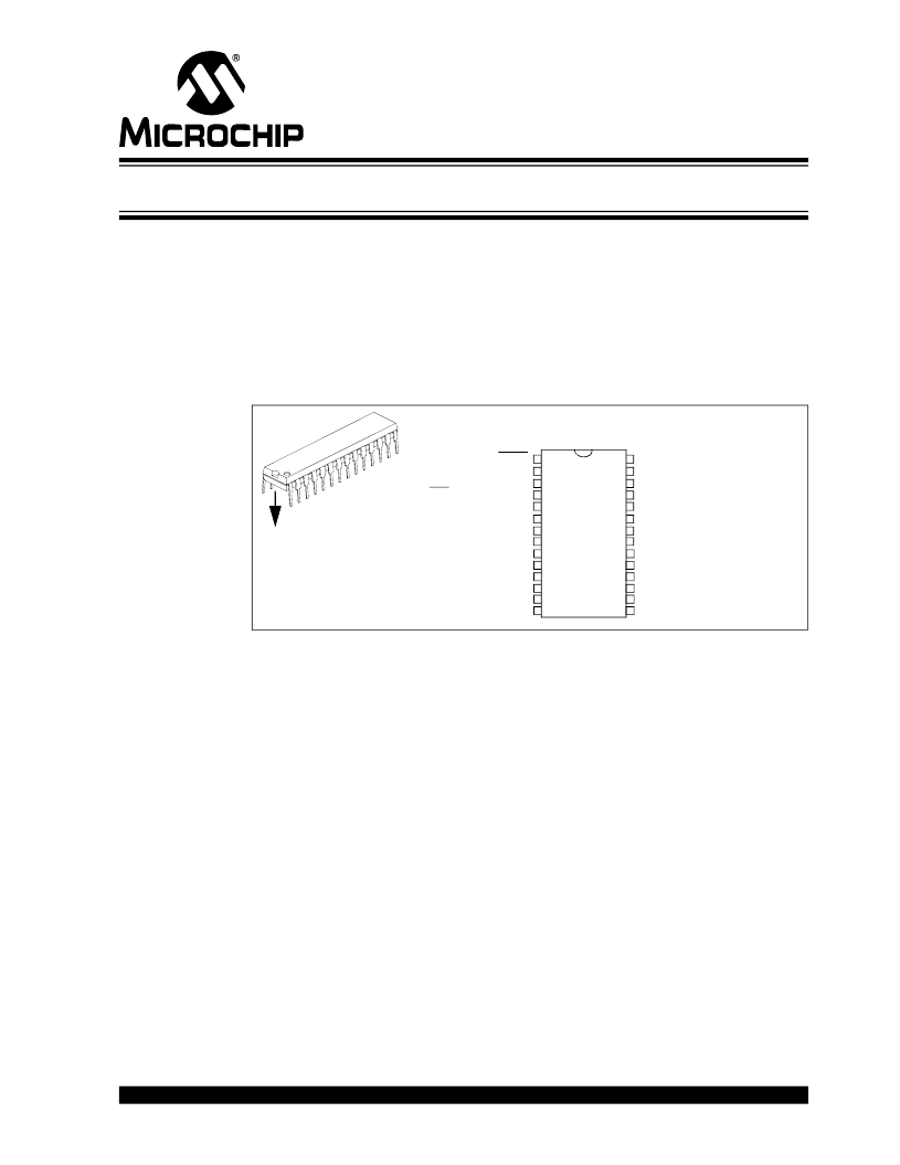
This chapter assumes you have chosen the dsPIC30F3013 for your application. The
dsPICDEM 2 Development Board supports a dsPIC30F3013 device in a 28-pin SPDIP
package, as shown in Figure 9-1. This device provides ten 12-bit A/D (100 ksps)
channels, two UARTs, an SPI module, an I 2 C module and 20 I/O pins. A sample
application program provides a software baseline for building your own embedded
solution.
FIGURE 9-1:
28-PIN SPDIP dsPIC30F3013
MCLR
EMUD3/AN0/V REF +/CN2/RB0
EMUC3/AN1/V REF -/CN3/RB1
AN2/SS1/LVDIN/CN4/RB2
AN3/CN5/RB3
AN4/CN6/RB4
1
2
3
4
5
6
28
27
26
25
24
23
AV DD
AV SS
AN6/OCFA/RB6
EMUD2/AN7/RB7
AN8/OC1/RB8
AN9/OC2/RB9
U1B1
AN5/CN7/RB5
V SS
OSC1/CLKI
OSC2/CLKO/RC15
EMUD1/SOSCI/T2CK/U1ATX/CN1/RC13
EMUC1/SOSCO/T1CK/U1ARX/CN0/RC14
V DD
IC2/INT2/RD9
7
8
9
10
11
12
13
14
22
21
20
19
18
17
16
15
U2RX/CN17/RF4
U2TX/CN18/RF5
V DD
V SS
PGC/EMUC/U1RX/SDI1/SDA/RF2
PGD/EMUD/U1TX/SDO1/SCL/RF3
SCK1/INT0/RF6
EMUC2/IC1/INT1/RD8
9.2
HIGHLIGHTS
This chapter discusses:
?
?
?
?
?
9.3
BOARD SETUP FOR THE dsPIC30F3013 SAMPLE APPLICATION
The dsPICDEM 2 Development Board supports dsPIC30F devices that have multiple
peripheral devices multiplexed on some pins. Therefore, the jumper set up of various
headers depends on which of the dsPIC30F peripherals are used by the application.
This section demonstrates how the board is set up for the dsPIC30F3013 device to
support the dsPIC30F3013 example software in the dsPICDEM 2 Development Kit CD.
Follow these steps to configure the hardware on the dsPICDEM 2 Development Board
for the sample application.
1. Disconnect the power source.
2. Remove any dsPIC30Fxxxx device currently plugged into the dsPICDEM 2
Development Board.
3. Plug the dsPIC30F3013 into socket U1B1.
? 2005 Microchip Technology Inc.
DS51558A-page 57
发布紧急采购,3分钟左右您将得到回复。
相关PDF资料
DM300019
BOARD DEMO DSPICDEM 80L STARTER
DM300024
KIT DEMO DSPICDEM 1.1
DM330012
KIT USB STARTER FOR DSPIC33E
DM330013
MICROSTICK DSPIC33F/PIC24H BOARD
DNET1
SURGE SUPPRESSOR ETHERNET RJ45
DR-8094
RACK DOUBLE 84"X20.25"X36" BLK
DR-IAC5E
INPUT MODULE AC 5VDC
DRIDC24A
INPUT MODULE DC 34MA 24VDC
相关代理商/技术参数
DM300018
制造商:Microchip Technology Inc 功能描述:DEMO BOARD ((NW))
DM300019
功能描述:开发板和工具包 - PIC / DSPIC dsPICDEM 80L Starter Demo Board RoHS:否 制造商:Microchip Technology 产品:Starter Kits 工具用于评估:chipKIT 核心:Uno32 接口类型: 工作电源电压:
DM300019
制造商:Microchip Technology Inc 功能描述:DEMO BOARD STARTER ((NW))
DM300020
功能描述:开发板和工具包 - PIC / DSPIC dsPICDEM MC1 Motor C RoHS:否 制造商:Microchip Technology 产品:Starter Kits 工具用于评估:chipKIT 核心:Uno32 接口类型: 工作电源电压:
DM300021
功能描述:开发板和工具包 - PIC / DSPIC High V Pwr Module RoHS:否 制造商:Microchip Technology 产品:Starter Kits 工具用于评估:chipKIT 核心:Uno32 接口类型: 工作电源电压:
DM300021
制造商:Microchip Technology Inc 功能描述:MODULE dsPICDEM MC1H 3 PHASE
DM300022
功能描述:开发板和工具包 - PIC / DSPIC Low V Pwr Module RoHS:否 制造商:Microchip Technology 产品:Starter Kits 工具用于评估:chipKIT 核心:Uno32 接口类型: 工作电源电压:
DM300023
功能描述:开发板和工具包 - PIC / DSPIC dsPICDEM SMPS Buck Demo Brd RoHS:否 制造商:Microchip Technology 产品:Starter Kits 工具用于评估:chipKIT 核心:Uno32 接口类型: 工作电源电压:
